1. Design sketch up and concepts on paper:
The design we came up with is based upon figure 1.1, 1.2 and 1.3. These designs were made University of Pennsylvania students for their project called Titan Arm. The designs are made to be ergonomically suited for the arm.
2. Research on Brachial Plexus Palsy and Muscular Dystrophy:
The group found that these disorders are fairly common diseases that not many people know about and not much has been done to assist people with disorders in such ways.
3. Creo designs for brace parts:
The group members started and finished the three major components that make up the exoskeletal arm using Creo Parametric 2.0. (fig 2.1, 2.2, 2.3) Final calculations and assemblies to make the skeleton fit the arm however need to be worked on.
4. Research on Materials needed:
The project needs quite a few materials in order to have a complete functioning prototype. All the materials needed were listed as follows:
Aluminium blocks, linear actuator motor, ball joints, 9 volt batteries and movable mechanical parts like screws, bolts and wires.
5. Machine Shop visit:
A major part of the project has to be handled with machinery so a machine shop visit to familiarize the group members with the procedures necessary to request for work and view the tools and machines available was seen as necessary.
Design Inspirations:
Fig 1:
 |
| a. Hydraulic powered robot arm |
 |
| c. |
 |
| b. Titan Arm |
Fig 2:
 |
| Fig a. forearm brace design (perspective 1) |
 |
| Fig b. forearm brace design (perspective 2) |
 |
| Fig c. forearm brace design (perspective 3) |
Week 3:
Budget sorting:
All the materials that the group saw as necessary in the first week were searched up on websites and their prices were marked down to finalize a tentative budget.
Listing materials required for purchase:
Brass Ball Joints:
The following is the eBbay link to the silver tone metal rod end spherical ball joints necessary for the elbow joint.
http://www.ebay.com/itm/4Pcs-Silver-Tone-Metal-Rod-End-Spherical-Brass-Ball-Joint-M4-3x6x26mm-for-RC-Car-/311136445986?pt=LH_DefaultDomain_0&hash=item48712d6622
Linear Actuator Motor:
The following is the eBay link to the linear actuator motor which is commonly used as a window opener, but will be used as the motor for moving the arm.
http://www.ebay.com/itm/4-100mm-12V-330-pounds-Linear-Actuator-electric-motor-door-windows-opener-/191545213692?pt=LH_DefaultDomain_0&hash=item2c98fc02fc
Aluminium Blocks:
The following is a link to metaldepot through which we will purchase the required aluminium blocks that will be molded into the exoskeleton.
http://www.metalsdepot.com/products/alum2.phtml?page=tube&LimAcc=+&aident
Computer aided concept design sketch:
Krita was used to sketch the concept designs for the arm brace as seen in fig 3a and 3b
Fig 3:
 |
| Fig a. Anterior view of the arm brace |
 |
| Fig b. Side view of the arm brace |
Concept update:
More computer aided design concepts were sketched out using Krita and the the final Creo Parametric arm parts design were also created and assembled:
Fig 4a shows the upper arm section
Fig 4a - 4d shows the different perspectives of the assembled upper and lower arm parts
Fig 5a and 5b shows the proposed solution for back support if the user cannot handle the weight of
the arm brace.
Fig 4:
the arm brace.
Fig 4:
 |
| Fig a. |
 |
| Fig b. |
 |
| Fig c. |
 |
| Fig d. |
Fig 5:
 |
| Fig a. |
 |
| Fig b. |
Figures 5 a-b : Krita design of the arm brace as it would look like on a person.
Week 4:
Purchase of materials:
The linear actuator motor purchased from amazon arrived. The size of the motor was a bit larger than expected and there are doubts that the motor might be too big and heavy to be supported by the arm. This might force us to return this six inch model that we ordered in exchange for a four inch model.
The 12 volt battery required for this has also been ordered.
Start up on electrical design:
The electrical design of the powered arm is a crucial part of the project.
Required materials such as bread boards and wires have been accumulated. However, without the finalized motor, the resistors required cannot be obtained.
Week 5:
During the fifth week the electrical design was looked over at the lab with Dr. Fred Allen. He suggested some changes to the circuit that was proposed. With very little background in electrical circuitry both group members required some help which came in the form youtube videos.
Dr. Fred Allen suggested that the group use an Arduino microcontroller to control the functioning of the linear actuator motor. The group got an arduino and some basic circuit components like a breadboard, LEDs, button switches and jumper wires to get started with learning the Arduino environment.
The basic programming aspect was learned rather quickly as Anav had some programming background. Meanwhile, Son had completely finalized the mechanical design in Creo Parametric with only the engineering file to be readied to send to the machine shop.
After learning the basics of the arduino environment, the group realized that they needed a few additional components that they required in order to successfully make a functioning electrical system which are as follows:
H-bridge: this allows the switching of the polarity of the voltage supplied. This is needed to allow for a two way action of the motor.
Relay switch: The arduino works at a measly 5V while the motor requires a 12V supply. This will be possible by using a relay switch board which can handle 12 V of supply and using the arduino to control the switches.
 |
| Arduino Uno: The micro controller to be used for the electronic design |
Week 6:
The circuit design for the arms movement was finalized. For the circuit some in depth research was conducted to confirm how the arduino could be physically set up to effectively manage a high voltage and high current requiring motor such as the linear actuator motor that the group is using.
The new circuit consists of many electrical components compared to what was previously stated. These include the following:
1. Arduino UNO
2. Jumper wires
3. Button Switches
4. Relay Switch
5. 12 V Lead Acid Battery
6. H-Bridge
7. Resitors
These are the essential components that are required to complete the proposed circuit. The components that were previously thought were unnecessary were the relay switch and the H-bridge. The relay switch is need 1) to allow for a small delay between the input and the output. This is required to maintain the current fidelity of the circuit and 2) to allow for the addition of an external battery to supply for the output voltage required for the motor to function. The H-bridge is required for the two way functioning of the motor. The H-bridge is a circuit that allows for the polarity of the circuit to be switched and thus changing the direction of current in the motor which allows for the two way functioning of it.
Amazon link to the H-bridge required:
http://www.amazon.com/Adafruit-H-Bridge-Motor-Driver-Steppers/dp/B00NAY2URO/ref=sr_1_3?ie=UTF8&qid=1431537742&sr=8-3&keywords=h+bridge
Amazon link to the relay switch required:
http://www.amazon.com/DROK-Circuit-Electric-Current-Control/dp/B00DU7XEB2/ref=sr_1_4?ie=UTF8&qid=1431538434&sr=8-4&keywords=relay+switch
Week 7
As time for the final design started approaching faster, the group had not yet finalized on what material was going to be used for the design of the arm. By consulting with Dr. Allen, we reached a conclusion that the initially proposed aluminum would be too expensive, so for the prototype we decided to use wood that was laying around in the lab.
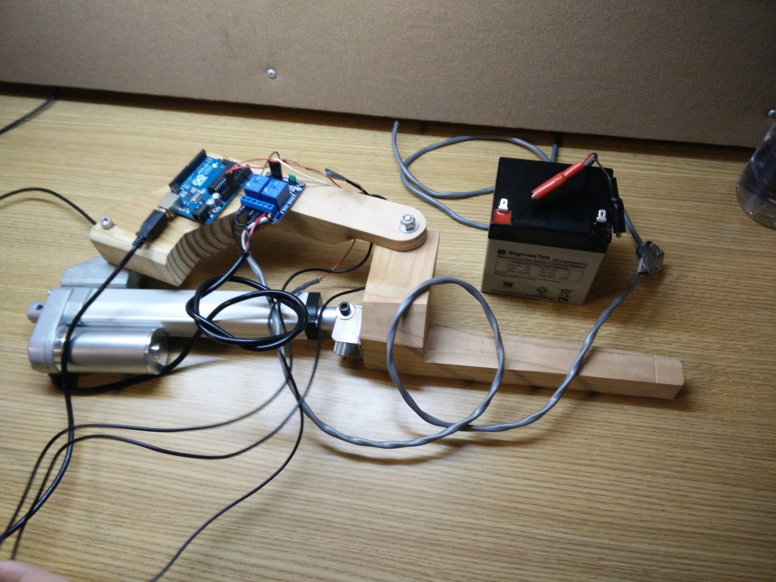
Essentially, the design would be the same. But strength and durability were to be compromised. Circuit design also proved to be a lingering issue. All the components of the circuit were finally delivered and actual implementation of the design also started. Below is a picture of the the circuit being assembled (Fig 7a):
 |
| Fig a: Arduino, circuit and 12V acid battery |
The actual arm was constructed with six hours spent at the Drexel Machine Shop. The machine shop provided the best atmosphere and all essential tools for building the arm. Using saws, files, glues and bolts the physical apparatus was finally created (Fig 8a-c). This is the group alpha build.
Fig 8:
 |
| Fig a |
 |
| Fig b |
 |
| Fig c |
 |
| Fig 9 |
Figures 7a-c: Images of team member Son with the device strapped on in a make-shift fashion with rubber bands.
Week 8:
With the mechanical design almost perfected, the only major component left to complete was the electrical control system. The control mechanism was finalized to be an Arduino controlled system that would switch between the polarities of the battery using relays. A lot of thinking and consultation with the electronics lab staff was done to reach this conclusion.
So, with the final prototype almost complete, the group also started to work on the pre-presentation that was due on week 9. With so many changes that occured including the right information on the presentation also proved a challenge.
Week 9:
The electrical design of the motor was completed on the second floor lab of Bossone, the Drexel engineering building. With the help of a few lab staff, the group managed to get the motor working in two directions using a relay board with two relays and two buttons.
The initial arduino control was not followed because it was not necessary for the two buttons to use a program. However, the Arduino was used to provide a 5 V source for the relay board. The group decided to still use the arduino because it was understood that the arduino would come in use when the group would follow through with the design after this term. It must be understood that this design would work if the arduino was replaced with a simple 5 V DC source.
Weight testing was also done during this week to find out the maximum weight that could be comfortably lifted.
 |
| Fig 9: Relay Board and Arduino Connection |
Week 10:
Final changes were made to the design and control methods were tinkered with. Originally, a glove fitted with buttons seemed to be the answer to the control mechanism but it was soon realized that using buttons on a glove and using the same hand to pick up an object would be counteractive. So, a last minute change was made from a glove to a control stick which was made out of wood. The buttons on the controller would allow the user to go between contraction or extension of the arm. The arm and all of it's components were tested for a final time at the recreation center at Drexel.
The final presentation was done successfully in front of the class, the professor of the course and a few visitors. The primary phase of the project ended successfully!
Video 10: Final Arm brace in action
 |
| Fig 10 a. |
 |
| Fig 10 b. |
 |
| Fig 11 a. |
 |
| Fig 11 b. |
Fig 11: Controller
No comments:
Post a Comment